
Installed kvar, effective kvar and switching stages
A single kvar figure does not describe an entire capacitor or filter bank. Output conditions, component ratings and switching arrangements should be read separately.
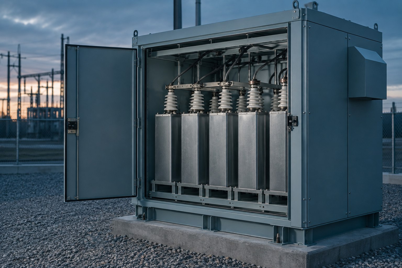
Nameplate total versus output
NEPSI distinguishes installed capacitor kvar at capacitor rated voltage from fundamental filter output at system voltage. Reactors and voltage ratios can make these values different. Specifications should state required effective output and its system voltage.
Stages versus steps
The number of physical switched branches need not equal the number of available output levels. As an original ideal example, 25 + 50 kvar branches offer three nonzero levels: 25, 50 and 75 kvar. Actual operation depends on controls and equipment constraints.
Clarify quotations
Request effective output, capacitor voltages, physical stage ratings and control-step size together. This reduces ambiguity in comparisons based solely on total kvar.
The numerical example illustrates stage logic only. It is not a filter design or purchasing recommendation.
NEPSI — Actual Kvar Output Versus Installed Kvar ↗
NEPSI — Step and Stage Size Considerations ↗
This content provides general information. Electrical installation work requires assessment by qualified technical personnel.
Explore this topic for your installation.
Share your existing system and technical question to discuss consulting.
Request a technical assessment ↗